Working with Evaluation Data and Files
This document presents a quick guide for evaluating and testing various features of CanalNET software. Users can open AutoCAD and load the sample file if they have it installed in their system. That will help to test production feaures as well.
It is also possible to evaluate with out opening AutoCAD. CanalNET can access the relevant data elements in the AutoCAD drawing file, and display network data fully. Drawing production features will not funciton, however.
You don't need AutoCAD to try CanalNet. You can use sample files to explore through the key features and fucntionalities.
Make sure you obtain a valid evaluation file from our team,. Sample files contain:
- an AutoCAD Drawing file (*.dwg)
- a data file (*.xsd)
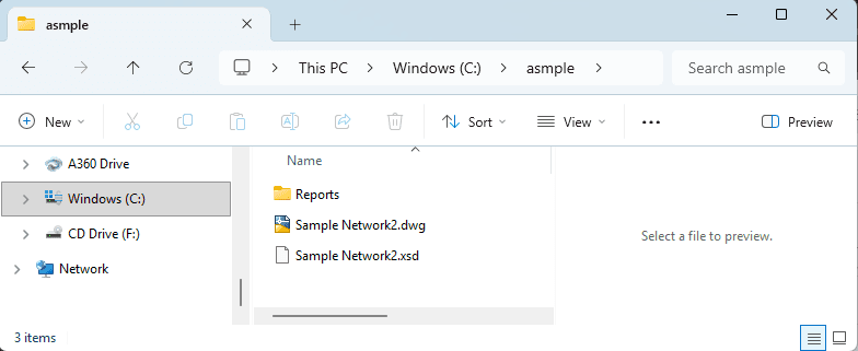
A file browser dialog, showing typical contents of a sample file.
Other system generated files (backups and startup files) may be included, but are not needed.
Note: Data from other users or sources may have some errors introduced because of improper use with out enough experience.
You can proceed to load the contents of the sample files as follows.
Start CanalNet product from your desktop. If you are evaluating, choose *Evaluate CanalNet+iCAD' option.
The interface has three view ports:
- Layout view port (bottom)
- Profile view port (top)
- Detail view port (bottom-right)
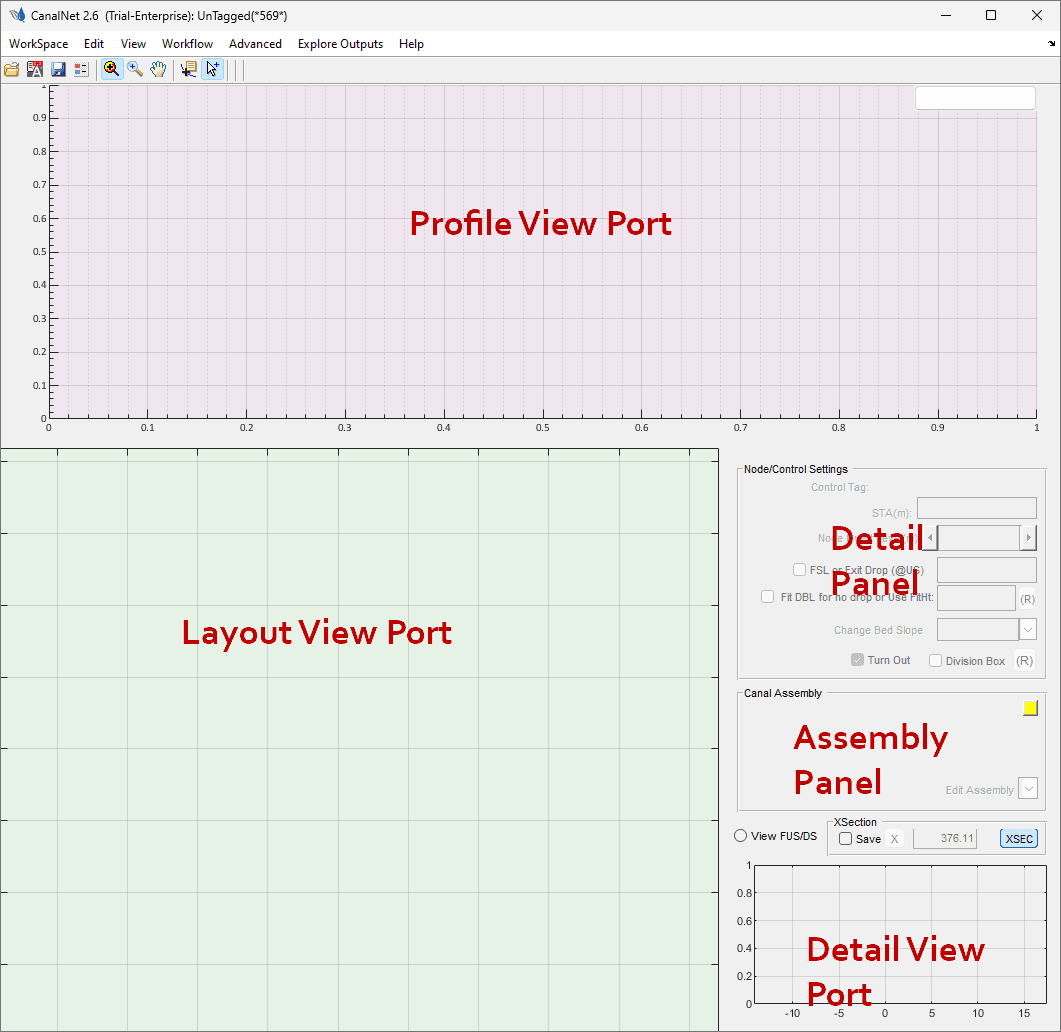
The CanalNet main interface and its components.
The interface also has the Detail Panel where data on selected network elemnts are presented, and can also be modified. The Asseembly Panel gives details on canal assembly data used to define the shape, construction and hydraulic properties of the canal sections.
The Detail View Port can be maximized using Ctrl+M keyboard short cut, and selecting Bigger Detail View item.
Openning the Sample Files
The sample files can help first time users to quickly explore features of CanalNet software. They can be opened folowing instructions, or watching the video guide.
Installation Tutorial
To Load the sample proejct data
-
Go to
Workspace > Load Network...menu command. -
On the prompt that Linking to AutoCAD Failed accept
Ok. -
The next prompt confirms failed status. Make sure to press and hold
fkey when pressing theOkbutton. Release the 'f' key as soon as the dialog disappears. -
The file browser dialog appears. Navigate to the locatio of the sample files, and choose the data file (with .xsd extension)
-
The 'Pick Dialog' lists available objects with canal network data. Choose one, and hit
Ok. -
The data is loaded in to the workspace.
Navigating the workspace
-
Scroll on any viewport to zoom in or out.
-
Ctrl+Ato zoom to extents -
Right-click and drag, to pan
-
Esc clears selections
-
Ctrl+Scroll makes a constrained zoom (zoom only in horizontal direction)
-
Selection - one canal route at a time. To select multiple canals, enable Multi-select using the
Toggle Multi Selecttoolbar item. When in this mode, right-click on a selected object and the object will be released. -
Change preset views from
View > View Mode...and selecting the desired preset.
Tip: Return to default view, and then recreate the deired view preset if some elements of the interface are not appearing/behaving as expected.
Adding topography data to the workspace
Start by setting the following project preferences, from the Edit Network Preferences toolbar button.
- Go to
Workspace > Surface Data > Load Hosted Datamenu item. - Ignore the AutoCAD Link Failed dialog.
- When presented with Missing Data Dialog, press and holf
fkey again (to indicate you are fetching data from a file, and not from a live AutoCAD session which is the default) while clicking theOKbutton. The file pick dialog will apear. - Choose the presented object. This object contains processed topography data ready for display.
The data is loaded in to the workspace. Confirmation is also shown on the menu item with a tick mark.
Note: Surface data, contrours, and regions of interest are processed using iCAD software, and you will not be able to change those while in CanalNET.
Right-click on the layout view, and choose Refresh Routes context menu, to ensure the contour map is below the canal route alignments - making selection and visualizaiton easier.
Now ready to explore the features of CanalNet upclose.
Exploring Features and Functions
Useful and powerful features in analysis and visualization are presented below.
Longitudinal view
Longitudinal view presents a key visualization foundational for all design and analysis works in a canal route. Look at the video and follow instrucitons to experience the features.
Selected VIsualizations in CanalNet software.
Click on any route to view its longitudinal profile.
Tip: If not appearing, make sure the
Multi-selecttoolbar item is in OFF state, and try again. When profiles (or vertical designs) are displayed, the name of the route is displayed on the top right.
On the profile view
-
click on Segments of canals to see the hydraulic and geometric properties on the detail pane. Edit the discharge of a given segment from
Edit Assemblydropdown menu in the Assembly Editor panel, and selecting Hydraulic Parameters. -
Click on Nodes (the vertial bars), to see the properties they influence. For instance change the slope of the canal upstream of the control as shown below.
-
Click on a vertical-drop, and move your mouse to a different locaion and click. The drop is repositioned.
Exploring VIsualizations
CanalNet uses numerous visualization tools and technics to enahnce project design, amalysis and documentation. Explore the various ways in which project data can be presented and understood by viewing below video, or following instructions.
Selected VIsualizations in CanalNet software.
Start by selecting a canal route, and updating its profile data from Explore Solutions > Data Tables > LSec Profile Data or Ctrl+L key board short cut. The table data is generated, also used for next visualizations.
-
View Annotations on the profil view port from
Explore Solutions > Annotations > Drop HeightsandExplore Solutions > Annotations > Lsec Details. A detailed view showing curve segment hydraulics and curve details is shown. You can hide them by going to the menu commands again. -
Annotate cut and fill works from
Explore Outputs > Annotations > VCUT+VFILL. Measure involved volumes dynamically, including between stations. -
Start cross-sections view using the XSEC button on top of the Detail View Port. A vertical bar will appear at the center of the Profile View Port. Click on the line, and move your mouse, and click on a desired location. The cross-section is generated. Use the
ESCkey to stop generating cross-secitons. -
View Dynamocs cross-sections by enabling the Dynamic cross-sections view parameter in Network Preferences.
Plan Views
Generating plan views is easy, thanks to the 3D profile data and detailed alignment information workflows. See below video or following instruction to generate views, and detect clashes.
Selected VIsualizations in CanalNet software.
First visualize the foot-print of the canal work.
- Start by updating the profile data.
- Enable daylight view from Network Preferences toolbar, and setting the Route day-light parameter to 'Enable'.
- Right-click on the Layout View Port, and choose
Refresh Routes. Zoom in to the canal roue to view changes.
Note: The shaded lines show the extents of the construction edges for all canals (whose profile data is uptodate.)
To create plan views:
- Make sure the desired canal is the current selected route.
- Request Plan Views of a given canal by selecting
Explore Outputs > Plan Views > Generate Plan View' orCtrl+W` key board shortcut. - Follow on-screen guidance, and make sure to choose a proper lateral exageration.
The plan view is generated for the entire canal route.
Note: For long canals, the graphic and text information for entire lengths can be too much for presentation. Instead, generate for selected segmens.
Explorting Quantity Estimates
Quantity estimates are created in a few clicks. Request reports as follows:
Selected VIsualizations in CanalNet software.
- Select the desired canal route, and make sure to update the profile data. Use
Ctrl+'L` keyboard shortcut for speed. - First explore the structures from
Explore Solutions > Data Tables > Explore TurnoutsandExplore Solutions > Data Tables > Explot Drops. This will extract data on the go. - Go to `Explore Outputs > Data Tables> Generate Route BoQ. Accept default generation parameters. Once complete, choose to open the report, and it is served in your default browser (e.g., Google Chrome.)
Next Steps
The above examples show selected use cases in designing and documenting canal network designs. It is loaded with more powerful tools and processes for complex design, batch data processing and bulk report generation. The sample evalaution files are intended for quick exploration, and ofcourse does not touch on AutoCAD integration features - the best part where users can automatically generate accurate, rich and complete drawings in a few clicks for entire project data base.
To continue to explore more:
- Registering on our customer portal to get access to complete documentation. Go to Customer Registration (opens in a new tab) and provide your details.
- Sign-in to this (top right of this page) to read the documentation on different chapters, and continue to explore the sample files (with or with out AutoCAD).
- Connect with us and be part of our evaluations support program. We provide quick guidance to model your choice of real life project from scratch and guide you to generating ready-to-share designs and reports - included in the 30Days evaluation period.
Want a license?
- Get your Enterprise Tier license (the most popular choice) on our website, and activate your product! Benefit from unlimited support, hands-on guidance when you need it critically.