Standard workflow
CanalNETOWORK allows for flexible design approaches and processes. However, due to high dependency of tasks on available data, it is recommended to adopt the below discussed workflow. Adopting this workflow is proven to offer optimal progress towards the final products in the shortest possible time.
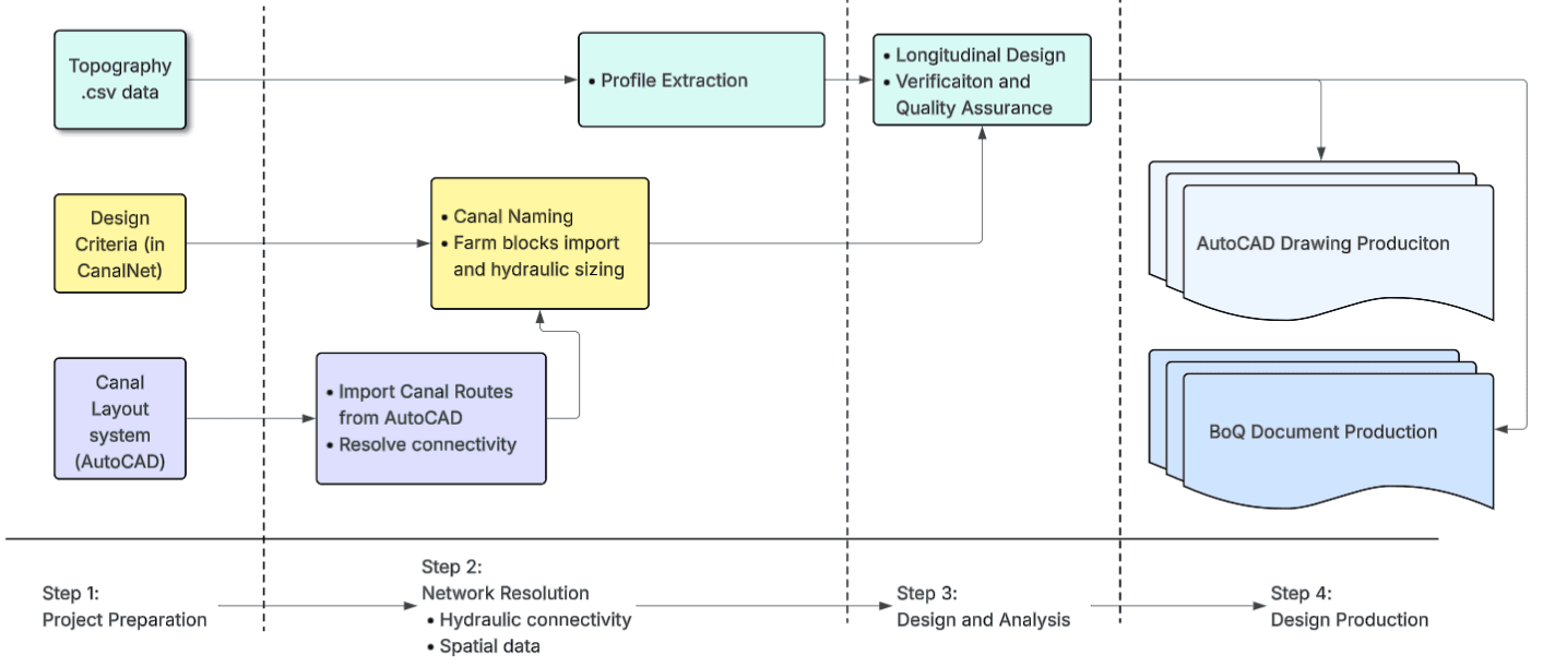
Figure: The standard flow of work when using CanalNet.
Input Data
The starting input data are AutoCAD layout map, Topo Cloud data, and Design Criteria.
The AutoCAD lauout map is required to have ONLY the polylines representing the canal routes. Contour maps, and other topgraphic features are not required. Unless needed for potential realigning, removing these additional data is recommended for speed.
Network resolution
Network resolution process ensures the connectivity between each route, through the automatic Node Creation task and available management tools (in Workflow > Nodes > ). In the process of resolving connectivity, editing the polyline objects representing individual routes is often unavoidable, hence the two way interaction shown. It is also important to check the profile of individual routes is always downgrade. This also requires adjusting the AutoCAD drawing.
Important Note: Network resolution task often forces change to AutoCAD objects. The AutoCAD file must be saved to maintain these changes frequently.
Network resolution also requires naming to be available. Use the maximum generation style available as a tentative source to complete this task.
-
Establishing Network is generating, based on the resolved network, the right naming and design criteria to each route in the network. The Design Criteria is required for this stage.
Here setting exceptions is expected for some routes, using
Edit > Route Exceptions > Set Exception.Also, farm block data is imported (or auto-estimated) to allow automatic sizing of each route as per the designated duty in the design criteria.
This is a key milestone in the progress towards longitudinal design task. Back up the network data at this stage for latter use.
Longitudinal Design
Profile extraction is the first stage of longitudinal design. The AutoCAD polylines representing canal routes are refined in the node resolution process. Linking the topography data source to the workspace, allows for bulk profile extraction for all canal routes.
With the profile data ready, and hydraulic sizing completed in earlier workflows, longitudinal design can now progress. Users interactively work with various design and analysis for each canal in the system, view and explore solutions, and visualize aspects of the proejct as needed.
Design production
The final stage is design production. At this stage the analysis and design work is compelted. Users can generate various outputs for publication, including:
- Detailed and accurate technical drawings
- Bill of quantity estimates
- and design reports
Iterative processes
It is often required to iterate through the above work flows, going back and forth as needed. That is perfectly possible with CanalNet. Users can add/remove routes, redesign routes, modify designs and generate context-specific quantities etc.