Design of Drops in CanalNETWORK
Introduciton
CanalNETWORK software can design drop structures using different methods. The software designs drops in two stages:
-
Crest Design: dealing with the design of the overflow area before the vertical fall, and the related hydraulic conditions.
-
Energy dessipator design: dealing with hydraulic jump conditions after the vertical fall, and the provisions required for safely dessipating the energy.
While the approaches commonly used for crest design are fairly similar, there are a number of established approaches to work out the energy dessipator design. CanalNETWORK currently has the following methods incorporated.
-
Chows (TYpe I)
-
Chows (Type II)
The hydraulic design and sizing for both types uses Chow's method. The differeces for both methods are shown below:
-
approach and exit canals
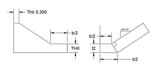
Figure: Inlet and exit canal forms for Type I (left) and Type II (right) structures
-
Stilling Basin wall
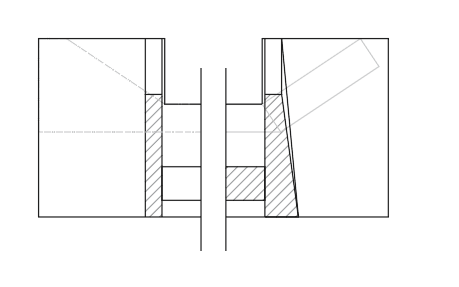
Figure: Stilling basin wall forms for Type I (left) and Type II (right) structures
-
Notch wall and stilling basin floor provissions
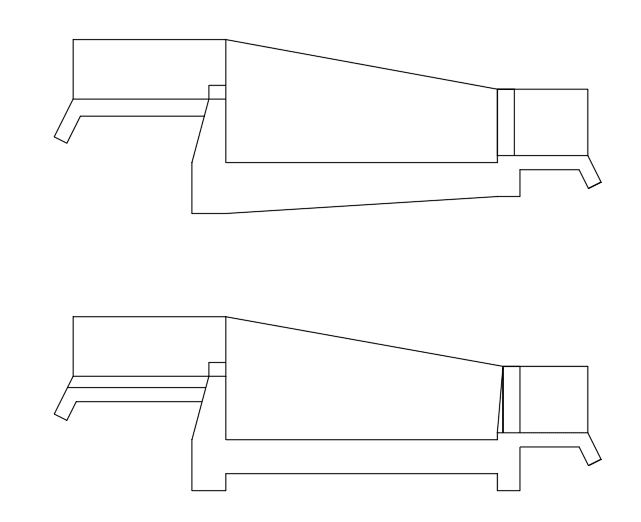
Figure: Stilling basin floor and d/s notchwall forms for Type I (left) and Type II (right) structures
The reference sources used in developing the algorithms for each method are indicated in brackets.
This guideline is primarily prepared to guide validation works with in our partners workflow, namely Ethiopian Construction Design and Supervision Works Corporation. In line with this, the discussion on design of energy dessipator focuses only on Chows method.
Upstream Crest Design
A rectangular crest is used for drops designed using this method. For this condition, the Top Width of the crest B is given by:
B= 0.55 * d ^1/2^
where d is the drop size.
The overflow discharge capacity is given by the governing equation:
For Q<14m3/sec
- Q= 1.835 x L x H^(3/2) x (H/B)^(1/6)
For Q>=14m3/sec
- Q=1.99 x L x H^(3/2) (H/B)^(1/6)
where L is the length of the crest (across the flow direction), and H is the hydraulic head over the crest. See the figure below.
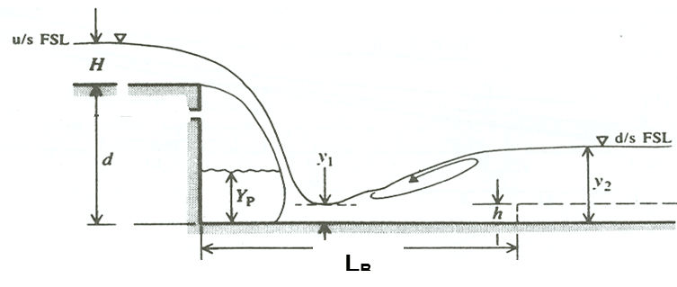
Typical hydraulic conditions over a drop structure.
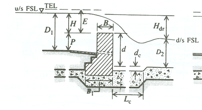
Crests of fall structures and upstream ydraulic conditions
Note: For Q>=14m3/sec the guideline recommends the use of a trapezoidal crest for the overflow section, hence the correponding modification in the discharge coeficient in the governing equation above.
Based on the above solutions, the critical flow depth, overflow depth are determined from:
q= Q/B
yc= (q^2^/9.801) ^1/3^
Ho= 1.5 * yc
This completes the upstream crest design, and establishes the parameters for the design of the energy dessipation provission below.
Design of Energy Dessipator
The design of energy dessipator provssion in Chows method relies on the Drop Number, calculated from:
D= q^2^/gh^3^
where
- g=9.81(m/sec2)
- h= d + ds, sum of the fall height and depth of sill
Then, the upstream and downstream flow depth is dtermined from
y1= d * 0.54 D ^0.425^
y2= d ** 1.66 D^0.27^
Based on this, sill depth is determined from
a= max (amin , y2/6)
Post impact length and 'unaided' jump length are determined from
Ld= 4.30*D0.270d
Lj= 5 (y2-y1)
and
L= Ld + Lj
The width of the basin is determined by providing a fixed amount of 0.10m (aplit on both sides) to provide for aeration.
Wb = Bw+0.10
Finally, the appron thickness is determined from considering the maxium uplift pressure magnitude and a unit weitgh G of massonry or concrete taken as 2.2;
tb= (Ho + d + a)/(G-1)
Nominal downstream and upstream cutoff depths are provided as follows.
du= dd= 0.30
Length of approach and exit canals are provided usinhg
Lp= 1.2 + 1.5 q^1/2^.
All dimensions for basin length, basin width, appron thickness, and protection length are finally rounded to 0.05 meters.
Dimension Tables
A typical output table for drop design data is extracted from Explore Solutions > Data Tables > Explore Drops as shown below.
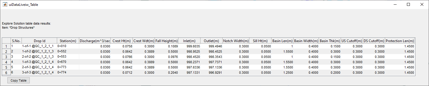
Figure: Typical output of drop design data for Chow Type I drop
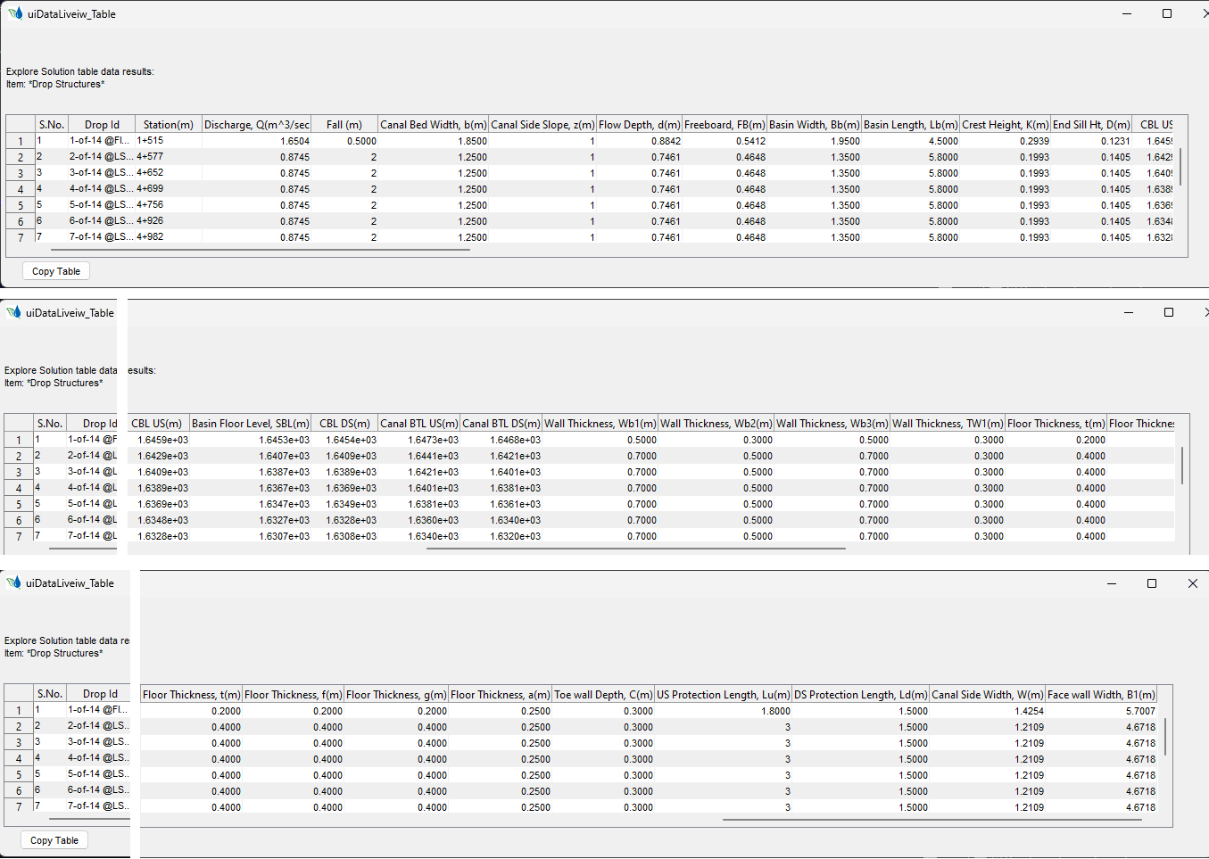
Figure: Typical output of drop design data and dimension table for Chow Type II drop
Drop Design Settings
Many of the design tasks carried out to size the different components of the drop depend on drop_designSettings in Preferences. These can be adjusted to fit specific site conditions.
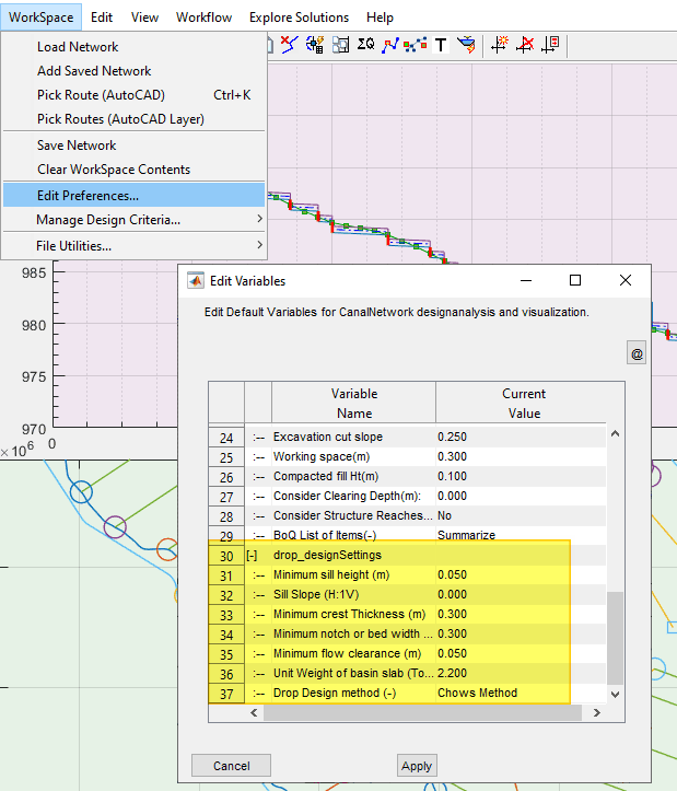
Note: These settings apply for the entire network of canals.
BoQ calaculation for drops (Chow I)
For the calcualtion of volumes of work for drops, the following procedures are implemented. The starting points are user provided values for Control BoQ Settings in Workspace > Edit Preferences.
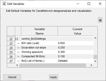
Contents of the Control BoQ Settings variable group
where:
B/H Ratio (Wall): ratio of height to width to determine the thickness of vertical wall of the drop at foundation level (default 0.65)
Excavation Cut Slope: Slope of vertical excavation from surface to foundation level (default 0.25)
Working space: desired space to maintain for working space, set by default to 0.30m
Compacted fill Ht: Height of compacted back filll material required on excavated bottom, and below the foundation block. The compacted fill area reported considers 0.10m width application in excess of the foot print of structures on all sides.
The calculation of quantities is carried out based on the following schematic diagrams:
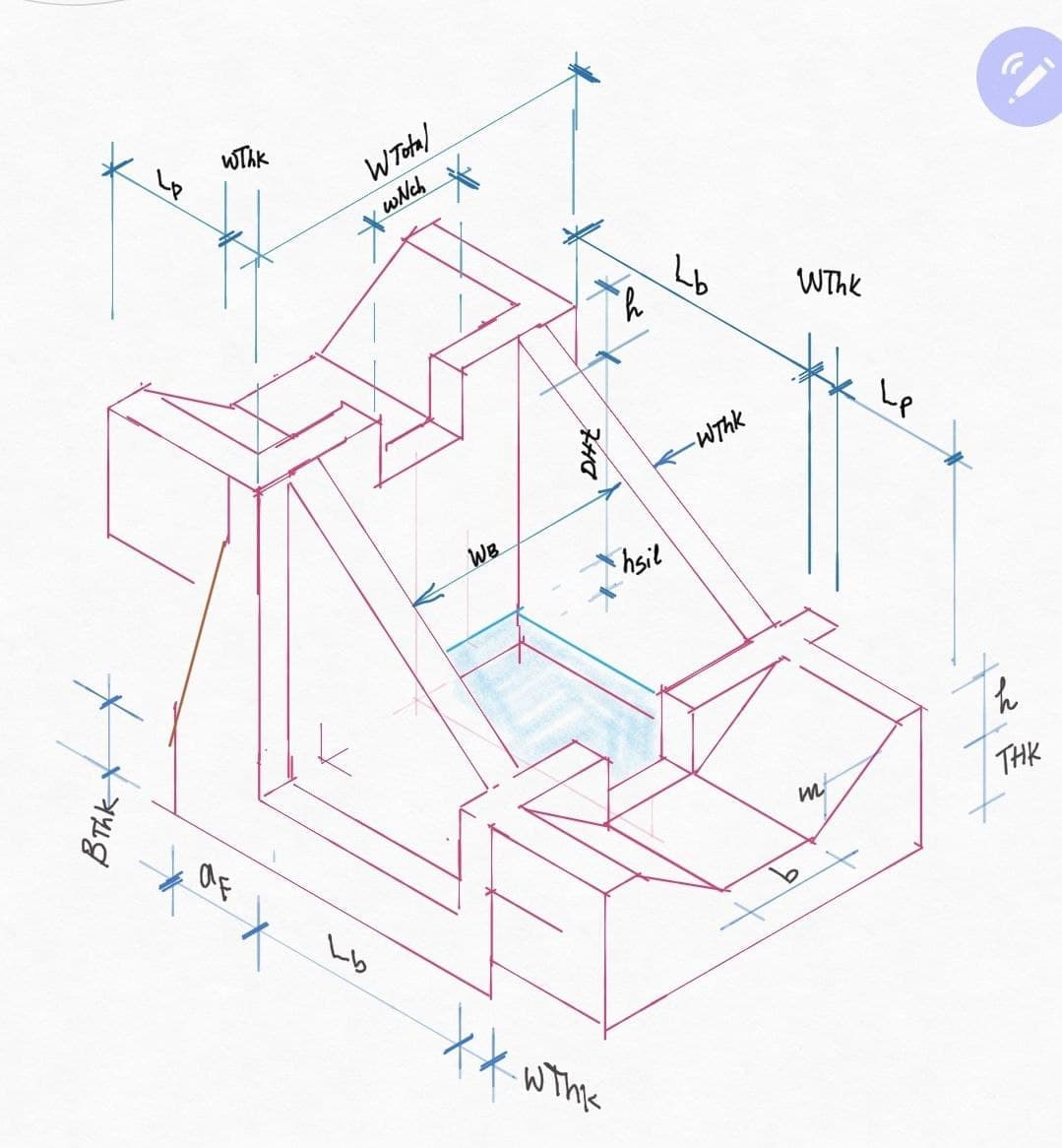
Isometric view of a Chow TYpe I drop structure as used for estimation of quantities in CanalNETWORK product.
Section view of a Chow Type I drop structure for quantity estimation.
Where:
WThk is the crest thickness, or the lininj thickness(Thk) of the canal, which ever is maxisum
aF= ()dHt + hSil) x b2h
Then:
wTotal= 2*(WThk + mxh)+b
Wb= b+2xmxh + 2xThk or Wb+2xWThk, which ever is maximum
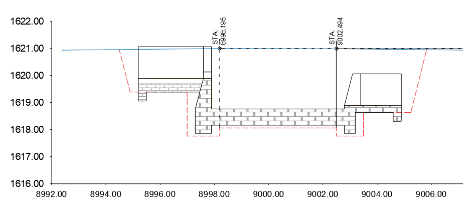
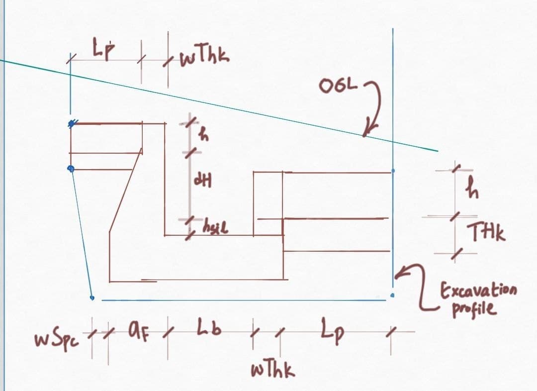
Figure: Earth work cut profile for Type II drop structure
The structural volumes are estimated for:
-
the approach or inlet canal at upstream end
-
the exit canal
-
upstream, and downstream notch wall(s)
-
The stilling basin, which also consists the foundation slab and the stilling basin walls,
-
for upstream and downstream cutoff walls, as a function of WThk and WTotal.
Lining work quantity is also included for inlet and exit canals.
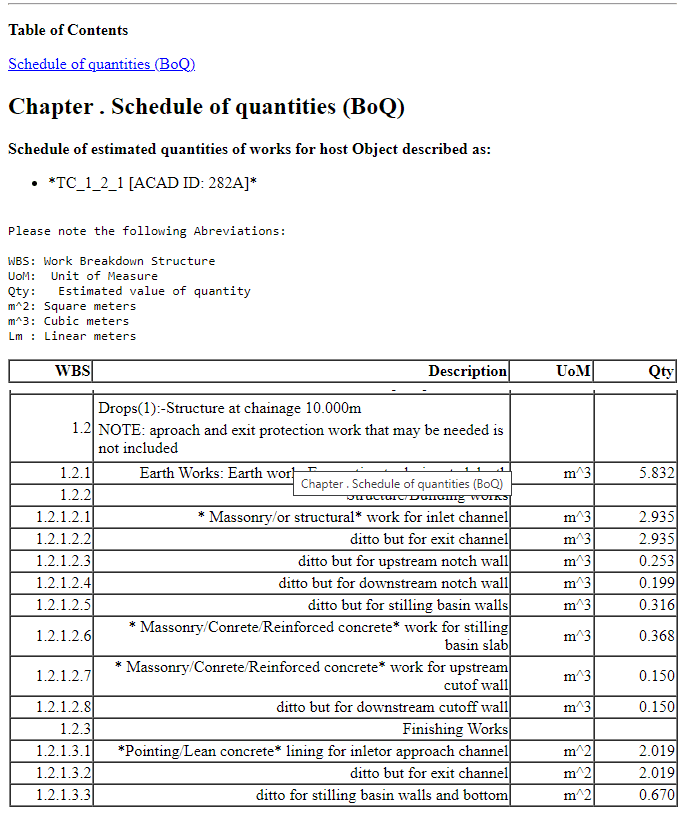
A sample BoQ for a drop structure contains the below informaiton in the standard report for the same.
END.
Reference: A Guide for Irrigation and Drainage Canal Structures Design - Drop Structures, Water Works Design and Supervission Entrepreise, Irrigation Drainage Land Reclamation and Flood Protection Design Team, May 2015, Addis Ababa.